Description
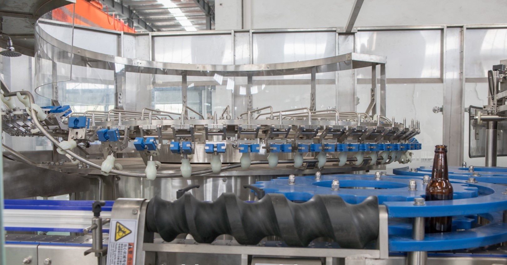
CARBONATED DRINK FILLING & PACKAGING LINE 6000 X 2000ML BPH
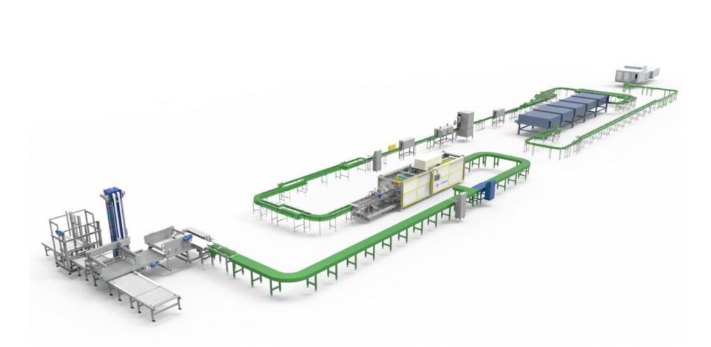
Price List:
| No | Name | Model | Capacity | Qty. | Unit price | Total price | Remark | |
| 1: Liquid Processing, 12 ton/hour | ||||||||
| 1 | High speed
Carbonation Machine |
INP-QHS12 | 10T/H | 1set | ※Siemens PLC+HMI
※RO water vacuuming system ※Carbonation system ※Proportional adjusting valve for precise mixing ※CO2 regulating & filtering system |
|||
| 2 | CIP back pump | YA12T | 20000L | 1set | ※Capacity:20000liter
Lift:24m |
|||
| 3 | Stainless steel
Electric cabinet |
1set | ※Air conditioning system
※Siemens PLC+HMI ※Siemens electric components ※Siemens elements |
|||||
| 4 | Automatic CIP system | CIP-3X4000L | 4000L | 1set | ※4000L Lye tank
※4000L acid water tank ※4000L hot water tank ※Siemens PLC + HMI |
|||
| 5 | Plate heat exchanger | 20m2 | 2pcs | ※20m2
※SUS316 contact part |
||||
| 6 | Cold water tank | LSG | 10000L | 1set | ※Three layers, insulated type | |||
| 7 | Chilling system | LSJ-460ADS | 1set | ※Screw cooling type
※Including cooling tower ※Pumps and pipes |
||||
| 7.1 | Cooling tower | INP-LQT | 50 ton | 1set | ※For cooling down the melted sugar | |||
| 7.2 | Cooling tower | INP-LQT | 100 ton | 1set | ※For chilling system | |||
| 8 | Steam boiler | INP-GL | 3000Kg/H | 1set | ※Italian Baltur burner
※German WIKA pressure gauge ※Diesel/Gas type ※Denmark Danfoss Pressure controller |
|||
| 9 | Pipe works | ※Outer surface and inner surface work handling
※On-site engineering welding ※Designed as shown in the drawing ※CIP system pipe works ※All Valves must be butterfly valves, Flanged gasket fittings, included in chilled water, CIP station to Machines, treatment to syrup prep to carbonator to filling part This must include the CIP and Return Line as well. ※Drainage system pipe works ※Cooling tower pipe works ※Chilling machine pipe works ※CO2 pipe works ※SUS304 drainage pipe works ※SUS gantry |
||||||
| Thermal insulation | ※Cooling tower pipe thermal insulation
※Chilling machine pipe thermal insulation ※Steam pipe thermal insulation is included |
|||||||
| Total price of section 1: | ||||||||
| Part 2. PET Bottle Blowing System | ||||||||
| 1 | Automatic 4 cavities Blow Molding Machine | INP4A-2L | 4000 bph | 2sets | ※Mitsubishi PLC
※Weinview HMI ※Parker high pressure blowing valve ※Festo Pneumatic cylinder ※Omron Sensors ※Schneider low voltage electric components |
|||
| Preform unscrambler | 4000 cph | 2sets | ||||||
| 2 | Blowing mould | 2000 ML | 4000 bph | 2sets | ※Aluminum alloy | |||
| 3 | HP Air Compressor
|
GY-4
|
3.6 m3/min | 2sets | ※3.6 m3/min, 30 Bar
※Austrian HOERBIGER high pressure valve train ※Siemens motor ※Holland Jorc waste discharging system ※Danfoss output pressure switch system |
|||
| Air dryer system for HP | 3.6 m3/min | 2sets | ||||||
| Air filter for HP | 3.6 m3/min | 2sets | ||||||
| Air Tank | 0.5 m3/min | 2sets | ||||||
| 4 | LP Air Compressor | DY-2 | 1.6 m3/min | 2sets | ※1.6 m3/min, 10 Bar | |||
| Air dryer system for LP | ING-2 | 2.0 m3/min | 2sets | ※2.0 m3/min, 10 Bar | ||||
| Total price of part 2 | ||||||||
| Part 3: Filling & Packaging, 2000ml PET bottle | ||||||||
| 1 | Rinsing filling capping
Tri-block |
INGF
40-40-10 |
6000 B/H | 1set | ※Siemens PLC+HMI
※Siemens VFD ※German IGUS sliding sleeve ※Sealing rings are made in Europe ※Centralized lubricating system ※CIP rinsing cup for CIP cleaning ※SKF or NSK bearing ※40 rinsing heads ※40 filling heads ※10 capping heads |
|||
| 1.1 | SUS316 Filling Valve | 40 pcs | ||||||
| 1.2 | Hepa system | 1set | ※Form a positive filling area | |||||
| 2 | Cap hopper | INP-SGJ | 6000 C/H | 1set | ※Belt type, with cap sorter | |||
| Cap sterilizer | INP-SGJ | 6000 C/H | 1set | |||||
| 3 | Light checker | INP-DJ | 6000 B/H | 1set | ※Energy-saving tank
※Strong penetration light ray |
|||
| 4 | Bottle warming and rinsing machine | INP-WPJ-10-2.2 | 6000BPH | 1set | ※Siemens PLC+HMI
※Siemens VFD ※10*2.2m ※Steam control system |
|||
| 5 | Blowing dryer | INP-CGJ | 6000 B/H | 2sets | ※SUS304, 3mm, supplied by POSCO, S. Korea
※two 7.5kW fans ※Air knife type |
|||
| 6 | Rotary type OPP labeling machine | INP-R8A | 6000 B/H | 1set | ※Siemens PLC
※Denmark Danfoss inverter ※USA Lion sensor for detecting label ※Germany SICK sensor for detecting bottles ※12 labeling heads ※YASKAWA Servo motors |
|||
| 7 | Automatic PE film shrink wrapping machine | INP-MB40 | 6000 B/H | 1set | ※Austrian B+R PLC and HMI
※German Sew Motor ※German Festo cylinder ※German Leuze sensor |
|||
| 8.1 | SUS304 mesh belt | 1set | ||||||
| 9 | Air conveyor with air fans | FC-1 | 13000BPH | 20m | ※SUS304, 3mm, supplied by POSCO, S. Korea
※2.2 kW air fan with air filter ※Electric cables sorting system ※Control cabinet |
|||
| 90 degrees turn | / | |||||||
| Fan | 3sets | |||||||
| 9.1 | Converging system | 1set | ||||||
| 10 | Flat conveyor with motors | FC-1 | 13000 B/H | 140m | ※SUS304, 3mm, supplied by POSCO, S. Korea
※SUS304 cable sorting sink ※German SEW Speed adjusting motor ※Lubricating system ※Subject to the final confirmation of the line’s layout |
|||
| Motor | 11sets | |||||||
| 90-degree conveyor turn | 6sets | |||||||
| 11 | Low pressure air compressor | DY | 4.0 m3/min | 1set | ※10 Bar
※Supplying the filling and packing line |
|||
| Total price of Part 3: | ||||||||
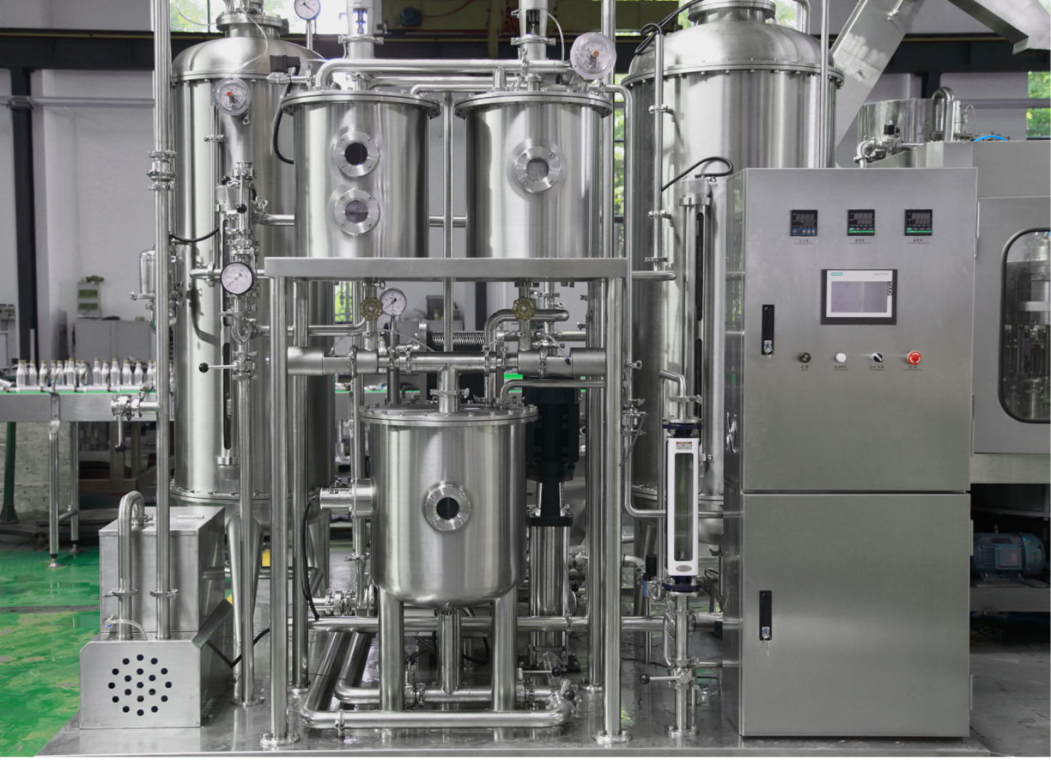
Carbonator
Description:
INP-QHS Soda mixer is an automatic equipment specially designed for the production of various carbonated beverages such as lemon, cola and juice. Compared with domestically produced products of the same type, it has the characteristics of complete functions, accurate mixing, convenient and easy to adjust, and meets sanitary requirements. The structure is novel and reasonable, the structure adopts closed system, and can meet the requirements of cleaning and disinfection. Produces carbonated beverages and can easily adjust production capacity and water to the perfect syrup ratio. In addition, the combination of electrical control and other devices has the characteristics of high degree of automation, coordinated operation, continuous production, good mixing effect and large production capacity.
Working principle:
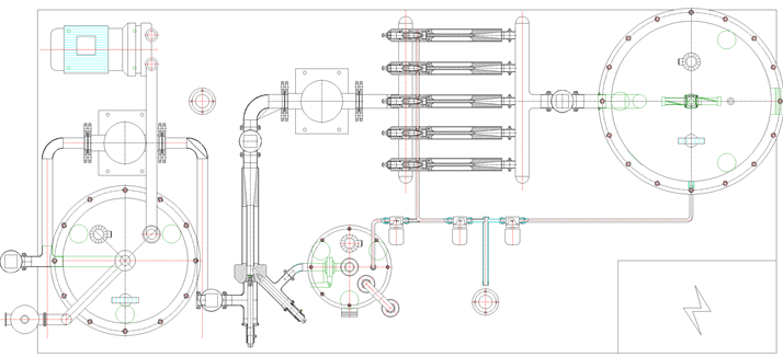
The INP-QHS automatic injecting gas-water mixer mainly consists of a vacuum section, a batching section and a gas-liquid mixing section.
- Vacuum section
The vacuum section consists of a closed circuit of the feed water inlet port by means of a solenoid valve, an air chamber, a vacuum pump and a vacuum tank equipped with a sprayer as well as a level controller.
- Matching section
The adjustment section consists of a ration pump, a slurry inlet line with a solenoid valve, and a syrup tank with a level controller. It consists of a syrup throttle valve and a venturi device. There are two adjustment handles with indicators on the venturi device. The size of the opening of the deaerated water and the sugar liquid outlet is shown, respectively. A certain amount of opening also reflects a certain ratio. For the amount of sugar required for a particular beverage, you can change the size of the opening by turning the sugar adjustment handle.
- Gas-liquid mixing section
The gas-liquid mixing section consists of a mixing pump, a CO2 inlet line with a pressure regulating device, a gas-liquid mixed venturi device, a soda storage tank with a level controller, and a soda water output line with a safety valve.
Technical parameters:
| Model: | INP-QHS12 |
| Capacity: | 12000 L/H |
| Mixing ratio(water:sugar): | 1:2 – 1:3 |
| Mixing precision: | ≤2% |
| Content of the CO2: | ≥2.0 times |
| CO2 supplying pressure: | 1-1.3 MPa |
| Heat exchanging area: | 30 m² |
| CO2 consumption: | 6 m³/h |
| CO2 purity: | ≥99.9% |
| Compressed air consumption: | 1.0 m³/ min |
| Compressed air supply pressure: | 0.6-1 MPa |
| Refrigerant: | Ethylene glycol solution |
| Refrigerant temperature: | -2 ℃ |
| Mixing temperature: | 25 ℃ |
| Pressure at purified water inlet: | 0.3-0.4 MPa |
| Pressure at syrup inlet: | 0.3-0.4 MPa |
| Temperature at syrup inlet: | ≤25 ℃ |
| Temperature at beverage outlet: | 1-2 ℃ |
| Pressure at beverage outlet: | ≤0.65 Mpa |
| Power: | 20.45 kW |
| Dimension: | 8000*6000*2600 mm |
| Weight: | 13650 Kg |
Hygienic pump
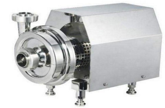
Technical parameters:
| Model: | YA25T/24 |
| Capacity: | 25000Liter/hour |
| Head: | 24m |
| Power: | 5 kw |
CIP cleaning system
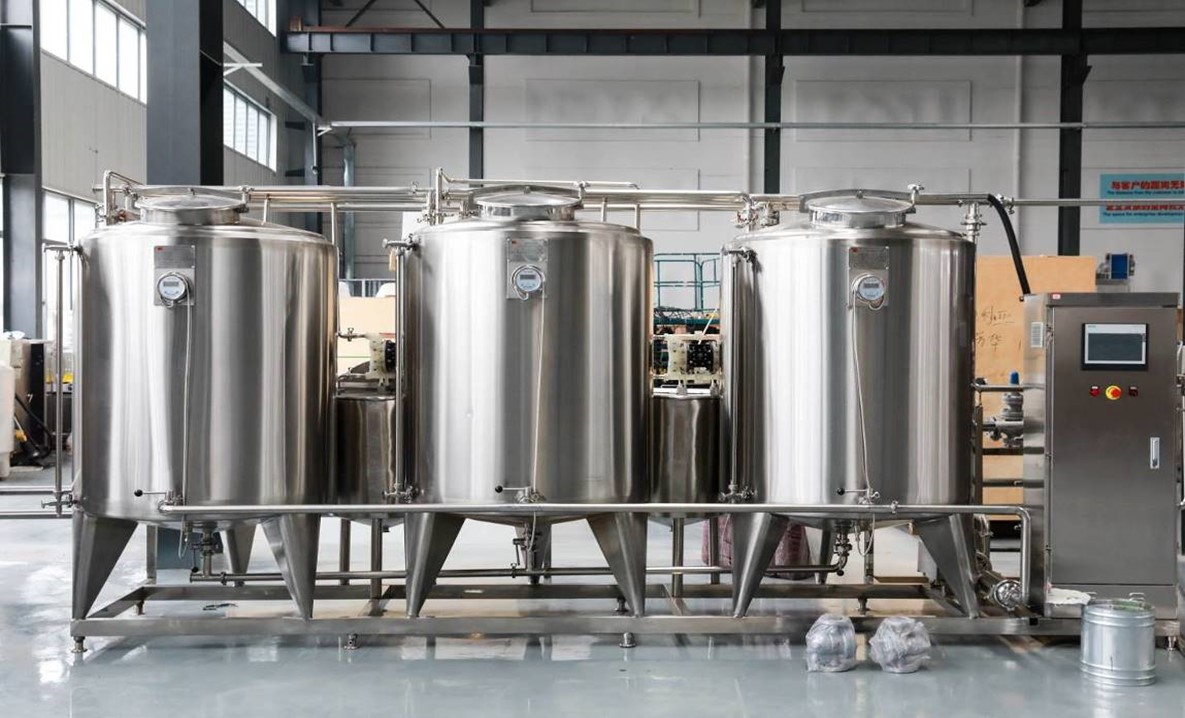
Description:
The whole system consists of water tank, alkali solution tank, acid solution tank, pump, plate heat exchanger
The CIP cleaning system is responsible for the cleaning of the filling machine.
The CIP cleaning system is fully automatic. All cleaning process parameters (cleaning time, acid-base concentration, cleaning solution temperature, cleaning method) can be set on the operating touch screen. When cleaning is required, specify the required cleaning equipment on the touch screen, select the cleaning method (three-step cleaning or five-step cleaning), and start the system, then the CIP equipment will automatically complete the cleaning process according to the preset program. Automatic recovery by acid, alkali and water.
The system has automatic hydration and automatic acid and alkali replenishment, automatic temperature adjustment, display temperature, concentration, liquid level, simulation process status, sound and light alarm function. There are also automatic and manual functions, various parameters can be modified on the touch screen. The manual function and the parameter modification function are password-protected.
Technical parameters:
| Model: | INP-CIP4000L | |
| Alkali tank volume: | 4000 L | |
| Acid tank volume: | 4000 L | |
| Hot water tank volume: | 4000 L | |
| Material of tanks: | SUS 304 | |
| Wall-thickness: | 2.5 mm | |
| Sanitary pump: | Water flow: | 20 m³ |
| Pump head: | 24 m | |
| Power: | 3 kW | |
| Plate heat exchanger: | Model: BP2-JB-4 | |
| Flow: 10000 L/H | ||
| Temperature change: 30°C → 85°C | ||
| SUS304 Stainless steel structure | ||
| EPDM sanitary pad, SUS316 plate | ||
| Alkali liquid pump: | 100 L/H | |
| Acid liquid pump: | 100 L/H | |
| Pipe fittings: | SUS 304 | |
Diesel type steam boiler
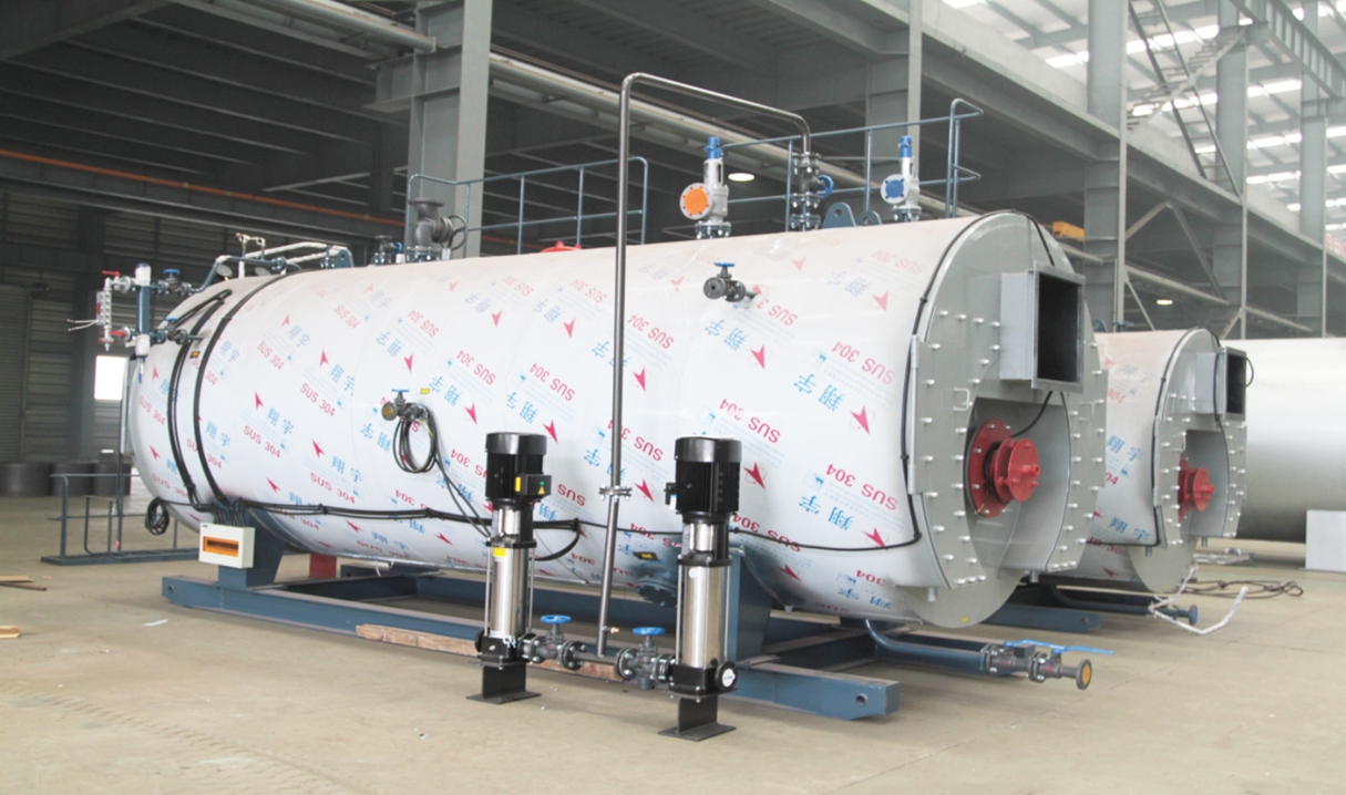
Features:
- The burner is supplied by Baltur, Italy.
- Quick start-up, can reach high temperature and pressure in short time.
- Nature circle, could handle large temperature change.
- With multi chain protection for water level and steam pressure.
- Vertical structure, small footprint, space saving and easy installation.
Technical parameters:
| Model: | INP-GL3000 |
| Steam Capacity | 3000 Kg/h |
| Rated working pressure | 0.7 Mpa |
| Real Working pressure | Can be adjusted |
| Hydraulic testing pressure | 1.05 Mpa |
| Diesel | 100 Kg/h |
| Thermal Efficiency | 92% |
| Power Supply | 400V / 50HZ / 3P |
| Saturated steam temperature | 170℃ |
| Main steam valve diameter | 40 DN |
| Safety valve diameter | 40 DN |
| Water in diameter | 25 DN |
| Sewage valve diameter | 25 DN |
| Chimney diameter | 250 DN |
| Overall dimension L*W*H) | 2530*1980*2650 mm |
| Weight | 2800 Kg |
Bottle Blowing Machine
Automatic 4 Cavities bottle blowing machine
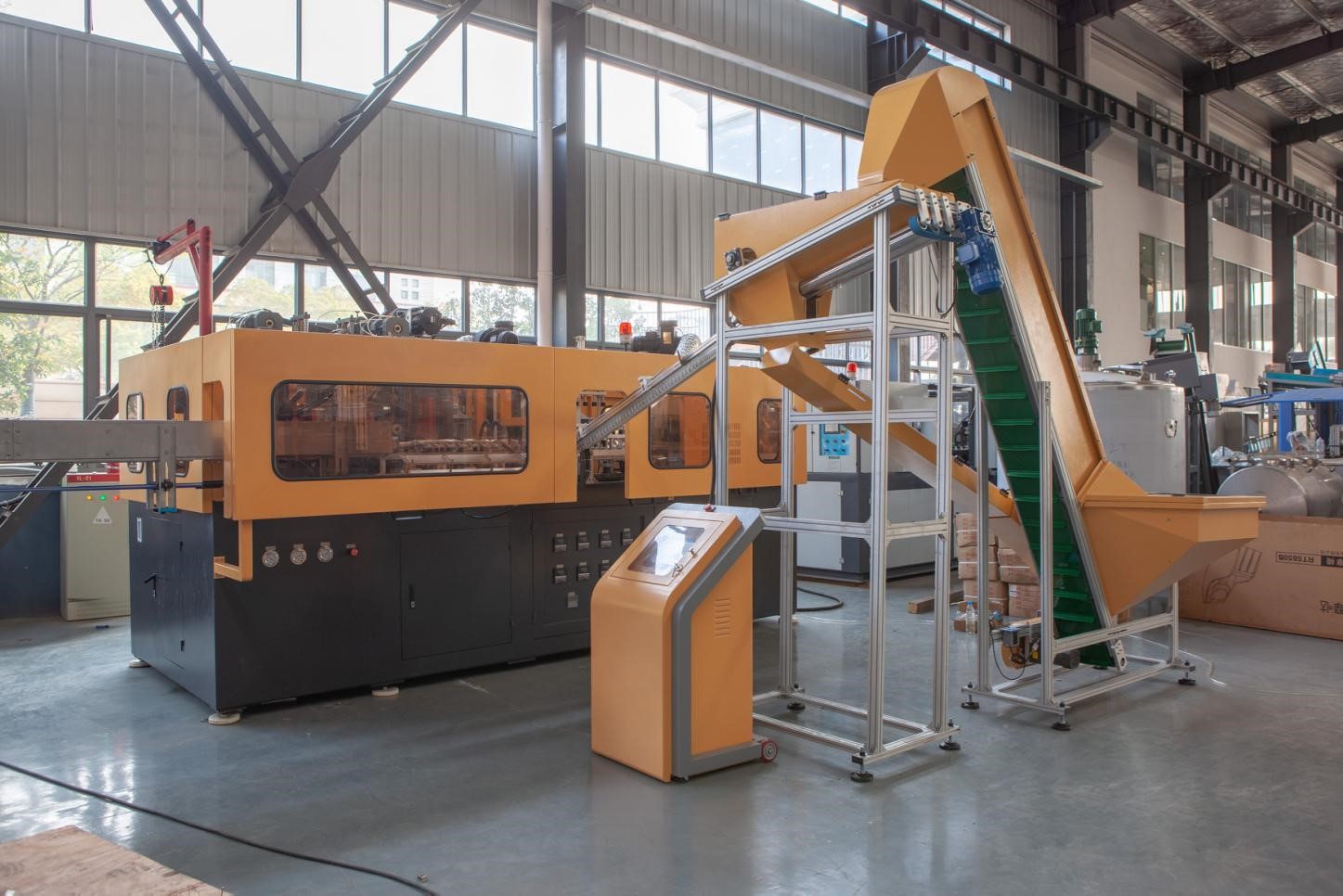
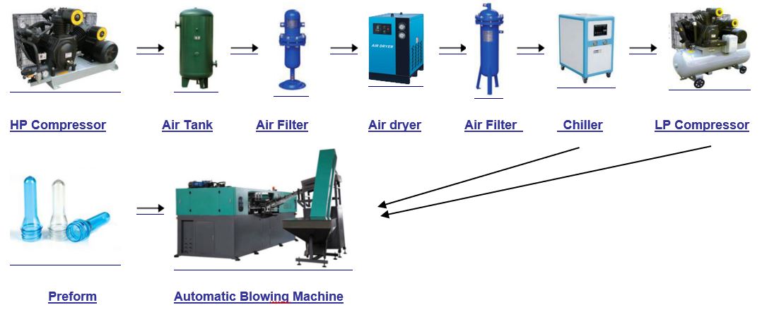
Flow chart:
Description:
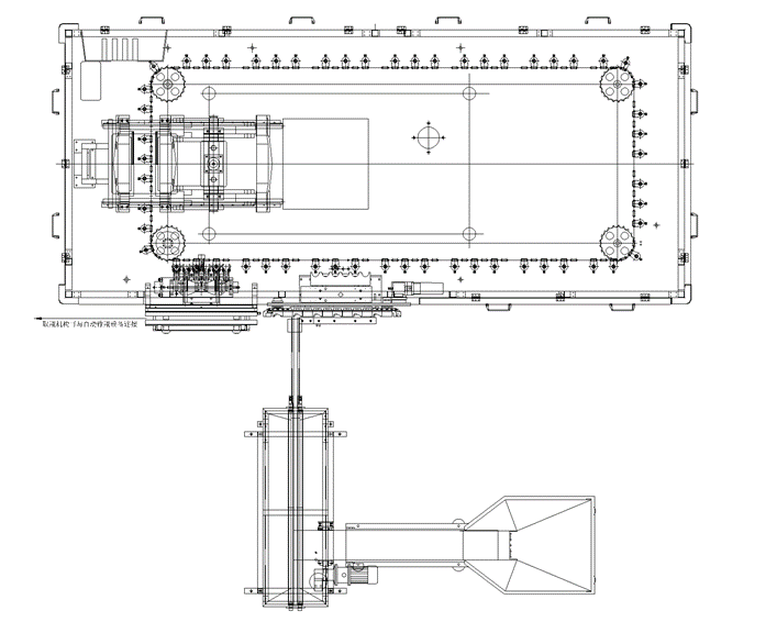
INPA4-2L Fully automatic blow molding machine is suitable for producing PET plastic containers and bottles in all shapes. It is widely used to produce the carbonated bottle, mineral water, pesticide bottle oil bottle cosmetics, wide-mouth bottle and hot fill bottle etc.
Mould Clamping System
Single cylinder clamps and locks the mould in a very short time, which avoids a very obvious parting line caused by mechanical clamping method.
Preform unscrambling system
While performs are aligned in the unscrambler, there is a photocell on each rail which controls the perform loading motor and aligning cylinder. All these ensure a very precise, high speed and compact mechanical system. And the whole system is very stable and energy saving.
Rigid structure
Rigid nozzle sealing, hard to wear, and well-sealed, no leak.
Standard components
Most of the parts are standard ones (such as chains, rails, cylinders, etc.), which ensures customer a reliable and easy maintenance.
General description
INPA4 automatic blowing machine adopts our most advanced blowing technologies. This machine is a fully automatic, high intelligent, stable and reliable blowing machine, with simple structure, and low energy consumption. It is very popular and well used in food, beverages, cosmetics, pharmaceutical industry.
Function and advantages
➢ Man-machine Interface control, easy to operate
➢ Automatic preform loading and unscrambling
➢ Preform hoppers
➢ Stable preform alignment, loading preforms according to capacity
➢ Close structure, low contamination
➢ Well preform heating system
➢ Stable rotating system
➢ Preforms are evenly heated, and easy to blow
➢ Low energy consumption, heating capacity is adjustable
➢ Recycling air cooling system in oven (option)
➢ Heating system is a mutual feedback and closed loop system, can works in a constant power output, without being affected by voltage fluctuation.
Preform loading, bottle fetching and outputting
All the preform loading and bottle fetching and outputting movements are finished by mechanical transfer arms, which avoid contamination.
Change moulds
The whole moulds changing takes only one hour.
High automation, low contamination
Fully enclosed design, finished bottle is transferred by mechanical arms and conveying belt, the whole production process avoids human contact, thus ensuring a healthy and cleaning environment which meets national health standards.
Stable and reliable performance
All the important parts, such as electric and pneumatic components, seals, bearings, and reducers, etc., are European or Japanese brands, ensuring a high qualified machine and reliable performance.
Human-machine Interface
Taiwan EV HMI, with a variety of parameters setting function, is easy to operate. Operators can modify the parameters while the machine is running, such as the pre-blowing, second blowing, blowing time, etc.
Easy maintenance
PLC communicates with machine through a specific cable connection. User can control every movement of the machine through this PLC. Once there is a failure, machine will alarm and display the problem. Operator can easily find the reason and solve the problem.
Safety
INPA4 automatic blowing machine is equipped with the following comprehensive mechanical and electrical safety devices to ensure the safety of operators and a long-term stable performance.
A) Safety of operators
This equipment is a fully enclosed structure, equipped with comprehensive and reliable guarding doors, which promises a very safe operation.
B) Safety of equipment
Multi-point detection technology maximized the protection of positioning system, clamping system, and stretching system.
Features:
- Stable performance with advanced PLC.
- Automatic preform conveyor to save human cost.
- Preform self-rotation and infrared pre-heater revolution assure the even distribution of heat, which improve the bottle shaping rate, increase the production.
- High adjusting performance to enable preheat the preforms perfectly by adjust the voltage control area in the PLC, which could adjust the temperature of the infrared lights in the pre-heater, and keep the proper temperature and humidity invariable.
- High safety with security automatic-locking device in each mechanical action, which will make the production into a perfect safe environment, in case of the breakdown in certain procedure.
- Introduce the FESTO air cylinder to avoid contamination and noise.
- Satisfaction with different atmospheric pressure for blowing and mechanical action by dividing the blowing action into three parts in the air pressure diagram of the machine.
- Strong clamping force with high pressure and double crank links to lock the mould.
- Two ways of operating: automatic and manual.
- Low cost, high efficiency, easy operation and maintenance etc., profited from the fully automatic technological process.
- Ideal cooling system make the finished bottles without any flaws.
Technical parameters:
| Model | INPA4-2L | |
| Blowing part | Cavity | 4 |
| Theory output | 4000 BPH | |
| Max.volume | 2L | |
| Bottle mouth maximum overall diameter | 28-38mm | |
| Bottle biggest diameter | 100mm | |
| Bottle maximum height | 330mm | |
| Power consumption | Light tube quantity | 32 pcs |
| Light tube power | 48 KW | |
| Air pressure specification | Work pressure | 7-9kg/cm2 |
| Low-pressure gas consumption | 1600L/min | |
| Blow bottle pressure | 25-35kg/cm2 | |
| Higher -pressure gas consumption | 1500Ltr/min | |
| Work pressure | 5-6 kg/cm2 | |
| Temperature range | 10℃ | |
| Consumption | 5000kcal/hr. | |
| Forzen water flow | 50L/min | |
| Machine specification | Size of the machine | 6000*5000*2600mm |
| Weight of the machine | 5.5 ton | |
Component list:
| Items | Supplier, Origin |
| PLC | Mitsubishi, Japan |
| Touch screen | Wienview, Taiwan |
| Servo motor | Mitsubishi, Japan |
| Servo drive | Mitsubishi, Japan |
| First-stage blowing valve | Parker, USA |
| Second-stage blowing valve | Parker, USA |
| Exhaust valve | Parker, USA |
| Stretch valve | FESTO, Germany |
| Action valve | REXROTH, Germany |
| Stretch cylinder | SMC, Japan |
| Mold clamping cylinder | SMC, Japan |
| Bottom drive cylinder | SMC, Japan |
| Mold locking moving cylinder | SMC, Japan |
| Mold sealing cylinder | SMC, Japan |
| Stepping chain | INPC, Taiwan |
| Mold clamping guild rail | HIWIN, Taiwan |
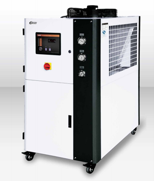
Air chilling machine
Description:
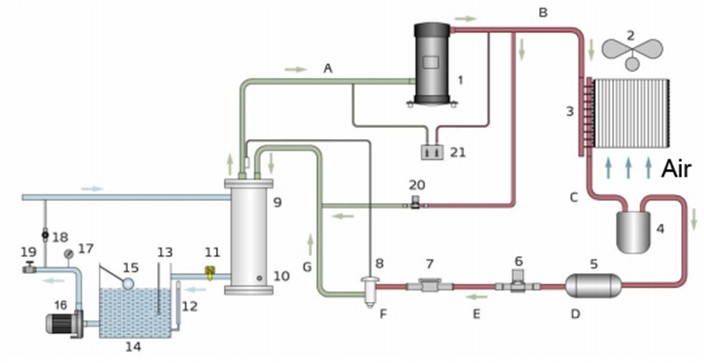
After the SIC-A series chiller is turned on, the compressor 1 starts to work, turning the refrigerant into a high-temperature compressed gas. The gas circulates in the direction to BC, enters the condenser 3 and exchanges heat with the air, changes from a gaseous state to a liquid state. while the heat is taken away by the air.
In the CDEF process, the liquid condensing agent coming out of the condenser passes through the liquid storage device 4, passes through the drying filter 5, get dried and filtered, passes through the liquid pipe solenoid valve 6, and the liquid crystal mirror 7 then reaches the expansion valve 8.
During the FG process, the high-pressure liquid refrigerant is throttled and depressurized by the thermal expansion valve, and the temperature is lowered.
During the GA process, the low-temperature & low-pressure refrigerant exchanges heat with the chilled water through the evaporator 9 to cool the chilled water to the preset temperature; the low-temperature gas refrigerant that comes out after the evaporator returns to the compressor, and finishes the recycle.
Technical parameters:
| Model | SIB-20A | |
| Cooling ability: | 52 kW | |
| 44,720 kcal/hr. | ||
| Compressor (output power): | 16.12 kW | |
| 20 HP | ||
| Refrigerate agent: | Weight: | 18 Kg |
| Controlling method: | thermal expansion valve control | |
| Type: | R22 | |
| Evaporator: | Shell type | |
| Condenser: | Type: | Finned condenser |
| Fan power: | 1.6 kW | |
| Water tank volume: | 230L | |
| Water pump: | Power: | 2.2 kW |
| Water flow: | 80/100/89 L/min | |
| Working pressure: | 2.0/2.6/3.5 kgf/cm² | |
| Total power: | 19.92 kW | |
| Actual power consumption: | 40-70% | |
| Pipe fitting: | Water inlet diameter: | 1.5 inches |
| Water outlet diameter: | 1.5 inches | |
| Water tank discharging hole diameter: | 1.5 inch | |
| Water tank overflow hole diameter: | 1.5 inch | |
| Protection devices: | Compressor: | Overload relay |
| Pump: | Overload relay | |
| Chilling circuit: | High/low voltage switch / anti-frost switch | |
| Water loop: | Bypass valve | |
| Power supply: | 380V 50 Hz | |
Component list:
| Items | Supplier, Origin |
| Contactor | Schneider, France |
| Thermal relay | Schneider, France |
| Thermal temperature table | Schneider, France |
High pressure air compressor
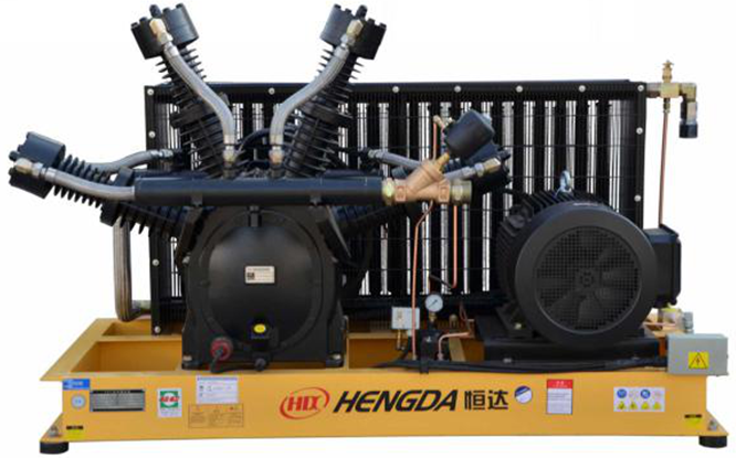
Description:
- The screws are supplied by German Loftoll company, The third generation V series, CK45 steel and new tooth shape design.
- The tooth curve formed by the adjacent two sections are smooth, the rotor contact line is short, the leakage triangle is small, the flow area is up to a streamline shape, the aerodynamic resistance is small, the specific power is low, and high efficiency can be obtained.
- Using imported high-quality carbon steel, after quenching and tempering, the material has good metallographic structure and mechanical properties, the tooth surface hardness is high, reaching HB200-240, good wear resistance.
- New generation high-efficiency motor
Optimizes the motor winding parameters, using imported high-efficiency materials, improving the control method, increasing the average effect when it is on high capacity running. During unloading, the current drops by more than 10%, and all indicators have reached the national second-level energy efficiency standard.
- The positive and negative proportional valves feedback 100% of the pressure signal to the servo cylinder and the recent control valve.
- The air intake control valve has adopted 0-100% stepless adjustment to the exhaust volume, so that the air supply volume is consistent with the air consumption volume, and the energy saving effect is optimal. The dimension control valve sets the blocking temperature and automatically adjusts the temperature of the lubricating oil to keep the viscosity in an optimal state, to ensure that the temperature of the exhaust gas is above the pressure dew point, and to extend the lube oil replacement cycle.
- The minimum pressure valve ensures the injection pressure required to lubricate the machine body, reduces the air flow rate of the oil separator, optimizes the separation of oil and gas, and has the function of a check valve.
- The high-efficiency oil and gas separator keeps the exhaust oil content below 3PPM.
- High-efficiency oil filter to filter out impurities in lubricating oil and provide clean lubricating oil for the head rotor bearing.
- The high-efficiency air filter removes dust and impurities in the intake air, so that the rotor head bearings and other heads can avoid damage.
- Equipped with differential pressure sensor when the differential pressure before and after the filter is blocked exceeds the preset value, it will automatically alarm to remind you to maintain or replace.
- PLC+HMI control
Technical parameters:
| Model | HG-4.8/35 |
| Capacity: | 4.8 Nm³/min |
| Rotating speed: | 690 r/min |
| Power: | 44 kW |
| Rated pressure: | 4.8 Mpa |
| Stroke: | 92 mm |
| Dimension: | 2200*1150*2350 mm |
| Weight: | 1900 Kg |
| Delivery connector: | 11/2” NPT |
Electric Components
| Items | Supplier, Origin |
| Motor | Siemens, Germany |
| High pressure valve train | HOERBIGER, Austria |
| Waste discharging system | Jorc, Netherland |
| Output pressure switch | Danfoss, Denmark |
| Contactor | Schneider, France |
| Breaker | |
| Thermo relay |
Compressed air-cooling drying filtering system
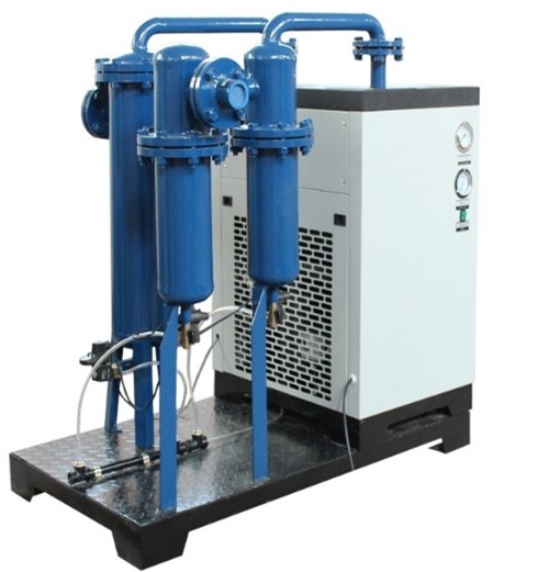
Technical parameters:
| Model | NTLN-4.8 |
| Capacity: | 4.8 Nm³/min |
| Working pressure: | 3.0 Mpa |
| Water filtering capability: | 99% |
| Cooling ability: | 1.5 HP |
| Dew point: | 2-10°C |
| Stroke: | 146 mm |
| Cooling agent: | R22 |
| Initial filter: | Oil ≤ 5mg/m³, Granule dia. ≤ 3um |
| First stage precision filter: | 4.8 m³, 3.0 Mpa,
Oil ≤ 1 ppm Granule dia. ≤ 0.3 um |
| Second stage precision filter: | 4.8 m³, 3.0 Mpa,
Oil ≤ 0.01 ppm Granule dia. ≤ 0.01um |
Filling & Labeling Equipment
Rinsing-filling-capping Tri-block
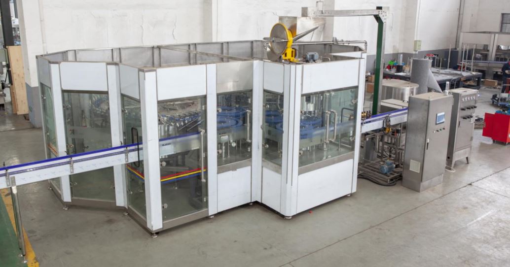
Description:
- Welded by SUS304. Product contact is SUS304 food grade;(SUS316 for option)
- High-efficiency rinsing-nozzles can spray water to any part inside the bottle;
- Corrosion-resistant bearings from NSK or SKF;
- Mechanical valve filling, flow meter filling, weighing filling or laser positioning filling for choice;
- Open design for gear transmission;
- Bottle transporting system is neck-holding design;
- Equipped with VFD control, more energy-saving;
- PLC control system is equipped;
- All electric components are supplied by the world-famous companies;
- French “ZALKIN” capping technology is used for higher performance;
- Capping torque can be adjusted accordingly;
- Cap absence can be detected and up-side down caps can be picked out;
- Online cap sterilizer for choice;
Technical parameters:
| Model: | INGF40-40-10 |
| Capacity: | 6000 B/H (2000ml) |
| Bottle height: | 120-310 mm |
| Bottle diameter: | 50-96 mm |
| Bottle mouth diameter: | 26-40 mm |
| Bottle type: | PET bottle |
| Cap type: | Aluminum cap |
| Material of the water dispenser: | Poly tetra fluoroethylene |
| Rinsing heads: | 40 |
| Rinsing time: | over 2 seconds |
| Filling heads: | 40 |
| Filling temperature: | normal temperature |
| Filling pressure: | 0.2-0.4 Mpa |
| Flow velocity of the valve: | 120-150 ml/s |
| Filling valve: | SUS304 |
| Product reservoir tank: | SUS304 |
| Main motor power: | 5.5 kW AC 380V 50Hz IP55 |
| Installation power: | 8 kW |
| Power supply: | 380V, 50HZ |
| Consumption of compressed air: | 0.8 m³/min (0.6MPa/H) |
| Consumption of aseptic water: | 0.4 m³/min (0.2-0.25Mpa) |
| Dimension: | 3900*4550*2300 mm |
| Weight: | 12500 Kg |
Component list:
| Items | Supplier, Origin |
| PLC | Siemens, Germany |
| Touch screen | |
| VFD | Siemens, Germany |
| Contactor | Siemens, Germany or Schneider, France |
| Thermal relay | |
| Switches | |
| Photoelectric electric sensor | Autonics, Korea |
| Pneumatic components | Airtac, Taiwan |
| Temperature sensor | OMRON, Japan |
| Bearing | SKF, Sweden or NSK, Japan |
Detailed description
A) Rinsing part
Features:
- Rotating type, used for rinsing containers of alcohol, beverage, pure and mineral water.
- Neck-holding catchers turn bottles upside down, and rinse them by aseptic water.
- Main structure, contact parts of the aseptic water and the cover are made of stainless steel.
- Bottle sensor is installed to prevent wrong-position bottles from being feeding in.
- Pressure gauge and valve stabilizer are installed on the water inlet pipe.
- Able to adjust the height to match the different-height bottles(have maximum and minimum height protection).
- Has aseptic water recycling system. For choice
- It automatically stops rinsing when bottle-absence detected, and restarts when bottle-presence detected.
B) Filling Part
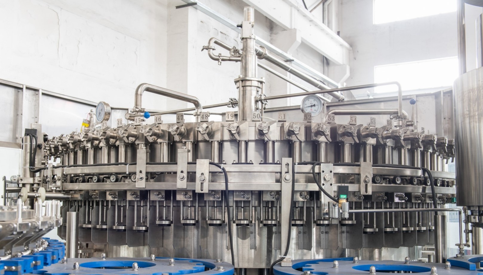
Features:
- Micro-negative filling technology.
- Insulated product reservoir, real-time temperature monitoring.
- Bottle-bottom holding structure to ensure bottle mouth and the filling valve connect seamlessly, avoiding product loss.
- CIP system is equipped, can be connected to the main CIP.
- The filler is able to adjust the height to match the different-height bottles.(Have maximum and minimum height protection)
- Open style gear transmission, easy maintenance.
- One nylon gear and one steel gear as a transmission unit, low noise, low weariness.
- German IGUS sliding sleeves are used on the bottle elevating rods, to minimize the weariness between the neck-holding part and the elevating rods.
- The motor is adjusted by the VFD.
- Bottle transporting system has simple structure, short changeover time to fit different bottles. Neck-holding method for transporting.
- PLC system controlled, errors can be displayed on the screen, such as: bottle jammed, cap absence.
- No bottle, no fill.
- The liquid level inside the filling tank is monitored by the sensor, ensuring stable filling.
·The key electric parts are made by the world-famous companies.
C) Capping Part
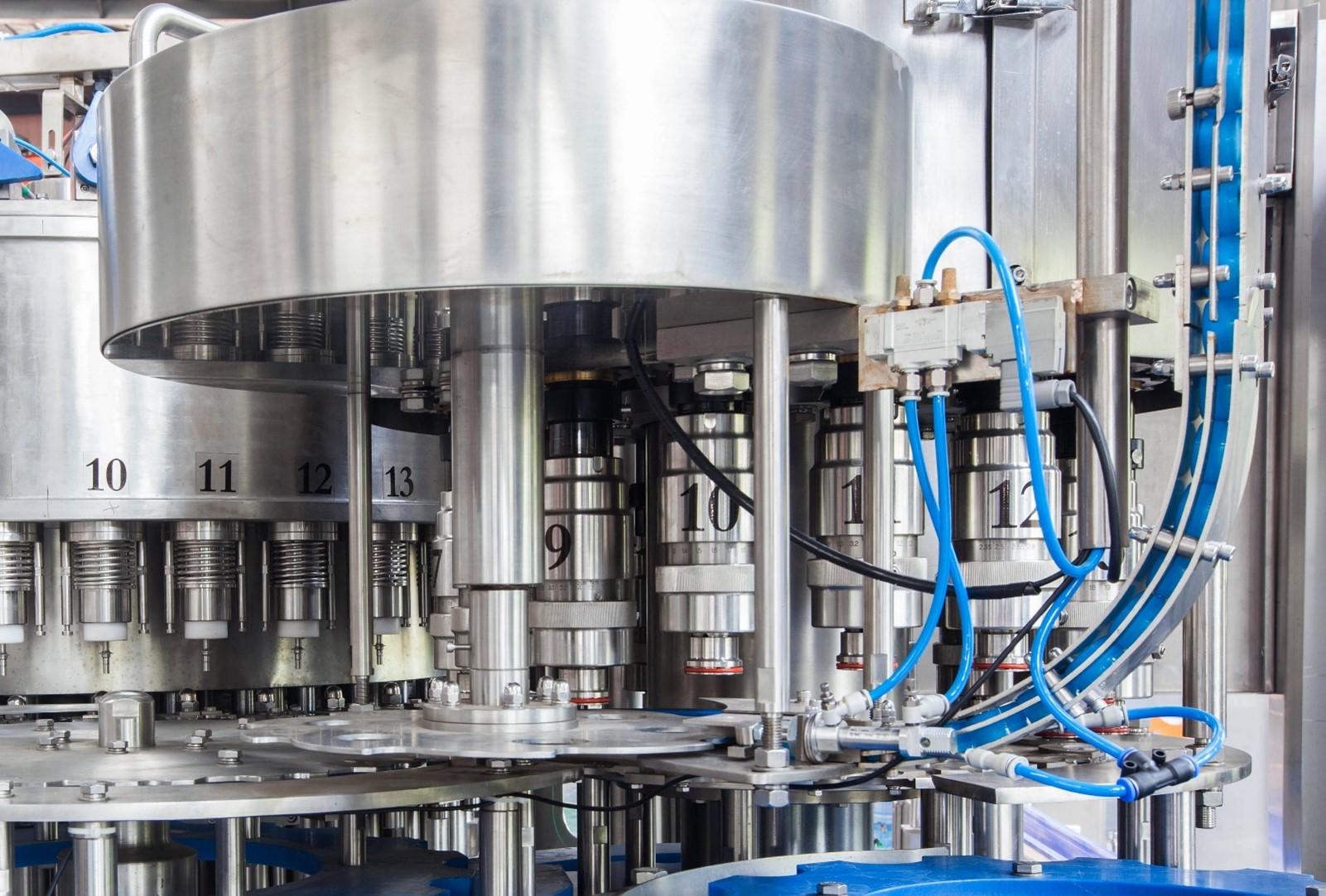
Features:
- Caps will be unscrambled in the silo, the amount is monitored.
- A flip-over adjuster installed on the slide to avoid up-side-down caps.
- Two photoelectric sensors installed on the slide to alarm the cap-absence.
- The capper is able to adjust the height to match the different-height bottles.(have maximum and minimum height protection)
D) Cap loader
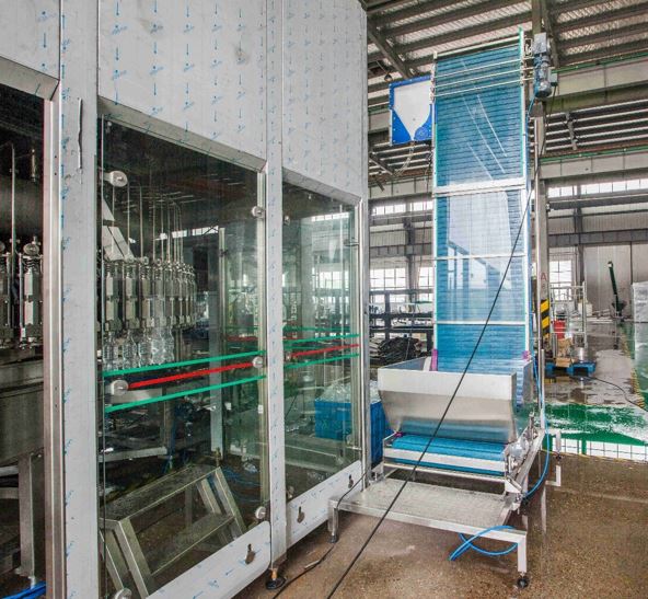
Features:
- Waterfall type cap sorting method.
- No damage on the cap.
- Transparent PC board for cap sorting.
- Equipment with AC motor and speed reducer.
- Indicator light for cap absence.
- Upside-down caps will be picked out and sent back to the hopper.
Technical parameters:
| Model: | INP-SGJ |
| Cap type: | Flat cap |
| Material: | SUS 304 |
| Conveying capacity: | 6000 caps/h |
| Power: | 0.37 kW |
Cap online sterilizer
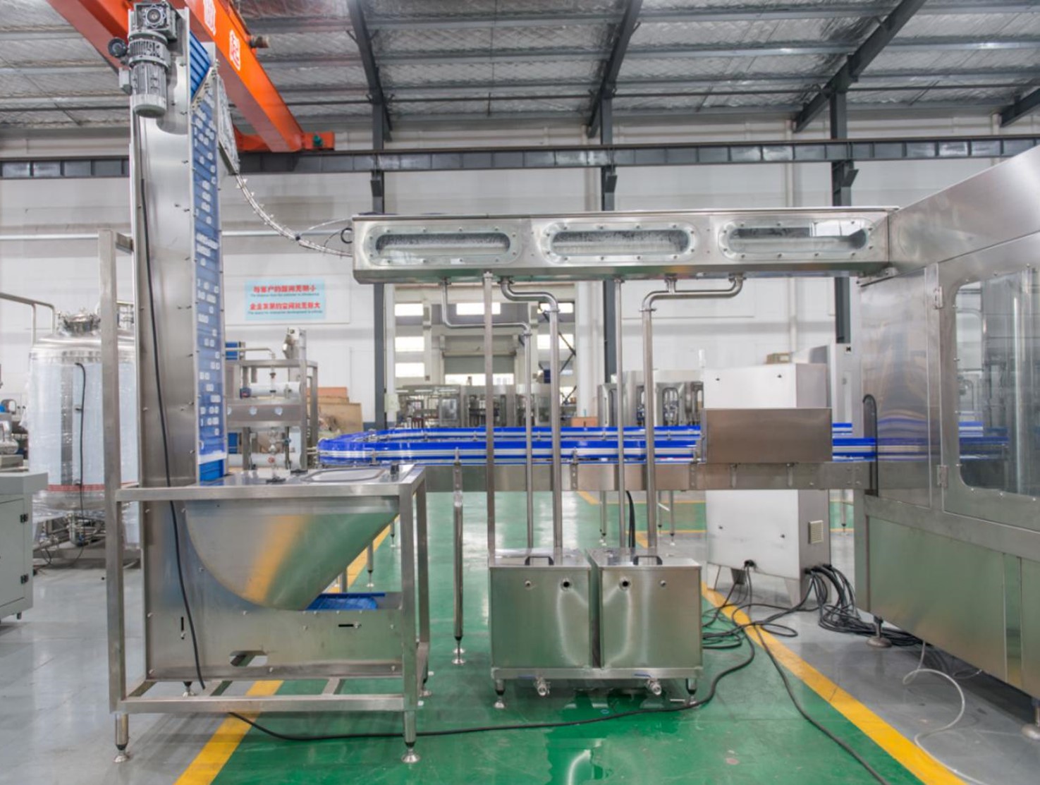

Description:
- Highly efficient centrifugal cap-unscrambling method, low wear.
- Cap detecting system provide signals to control the cap lifter.
- Special design on the cap unscrambler’s guild rail to prevent the up-side-down caps passing through.
- Caps would be sprayed by disinfecting solution, rinsed by aseptic water and dried by aseptic compressed air.
- Disinfecting solution tank has maximum and minimum liquid level, allowing replenishment.
Technical parameters:
| Model: | INP-XDJ |
| Disinfectant solution sterilizing time: | 15s |
| Aseptic water spraying time: | 5s |
| Aseptic compressed air-drying time: | 3s |
| Consumption of the aseptic water: | 1 Ton/H (0.2 MPa) |
| Consumption of compressed aseptic air: | 1000 L/Min (0.6-0.7 MPa) |
| Consumption of the normal air: | 800 L/Min (0.6-0.7 MPa) |
| Power: | 1 kW |
| Weight: | 900 Kg |
| Length: | 3500 mm |
| Manufacturer: | INPAKT |
Light Checker
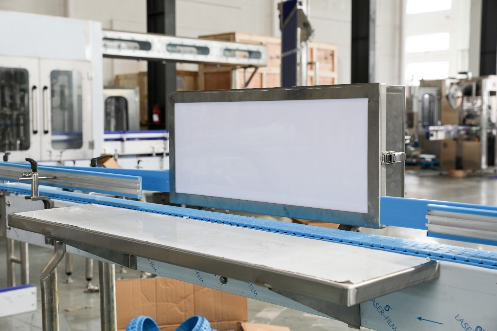
Description:
Indispensable equipment for beverage production line, eliminating defective products.
Technical parameters:
| Model: | INP-DJ |
| Lighting tube quantity | 3 |
| Power consumption: | 3*20 W |
| Material for framework: | Stainless steel 304 |
| Manufacturer: | INPAKT |
Bottle warming machine
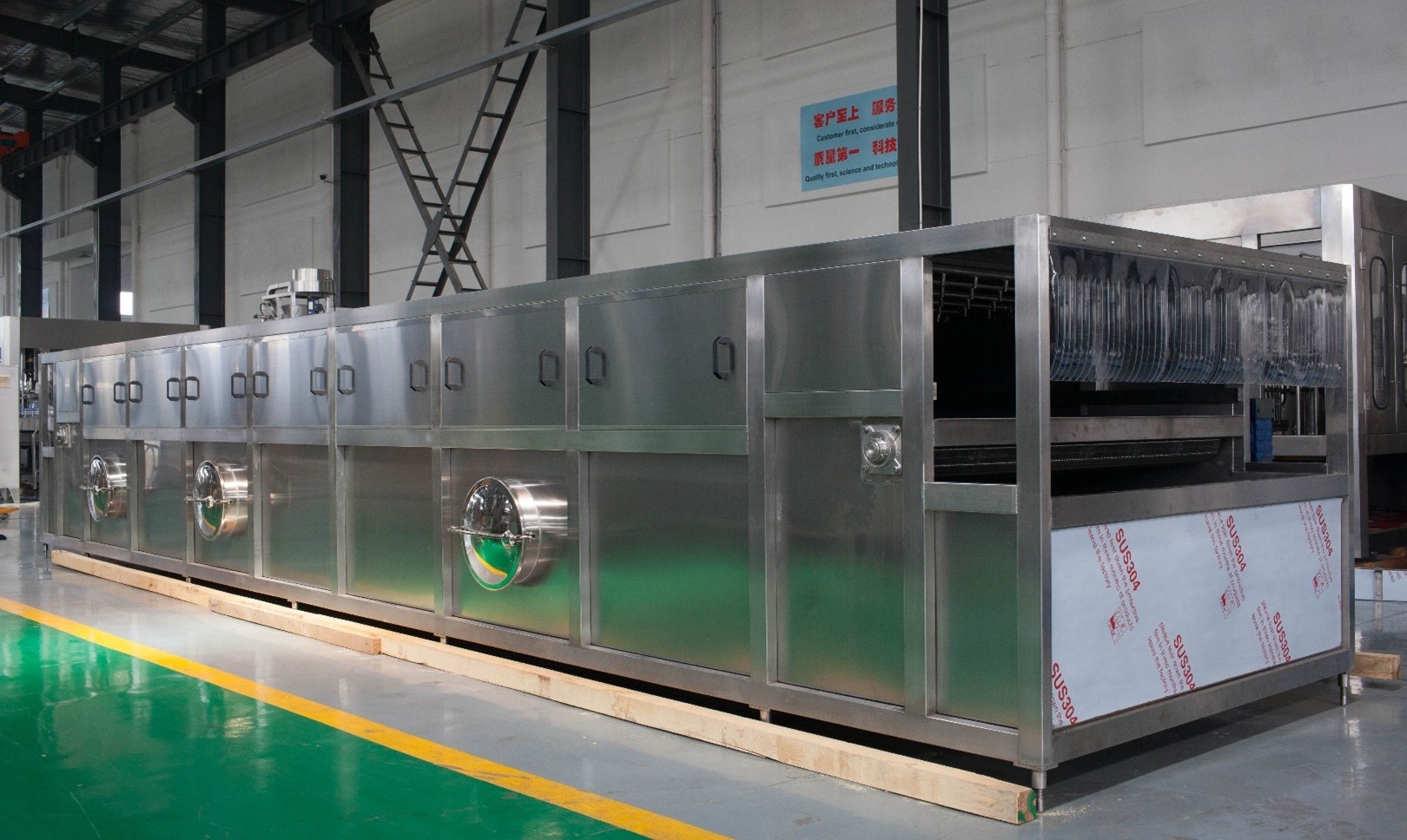
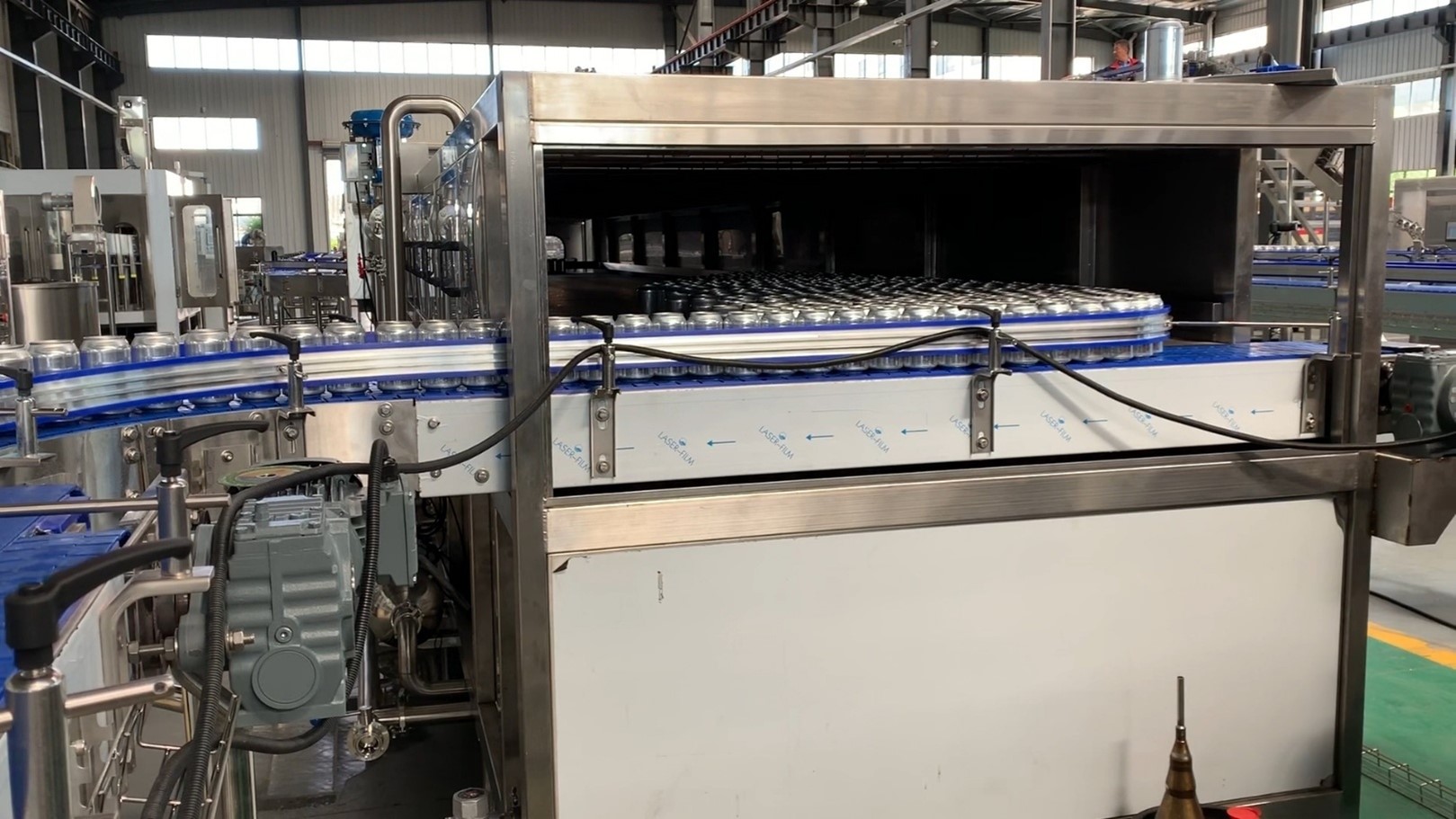
Description:
The cooling tunnel is used to warm bottles up to room temperature, for preserving taste and ensuring the quality of labeling and wrapping/packing processes. The machine sprays high temperature water onto the bottle to warm the bottles up. The cooling area is divided into five section, the temperature gradually increases while bottles pass by sections. When coming out of the tunnel, the bottles reach the room temperature.
Features:
- Highly reliable conveyor, flexible and convenient shifting system.
- The conveyor belt for conveying bottles is a high-strength plastic chain net with good strength and certain wear resistance.
- The main drive adopts a continuously variable motor, which can easily change the conveying speed of the conveyor belt.
- Efficient water spraying system.
- The machine adopts neatly and orderly arrangement of atomizing nozzles on the top of the chain plate to spray water to warm the parts of the bottles evenly, so that the spray water can be fully utilized and the spraying coverage area is large.
- Temperature control is sensitive and easy to set.
- This machine adopts temperature control system, high temperature control precision and sensitive response.
Technical parameters:
| Model: | INP-WPJ-10-2.2 |
| Capacity: | 6000 BPH |
| Material: | SUS304 |
| Motor power: | 0.75 kW |
| Dimension: | 10000*2200*1550 mm |
| Weight: | 8600 Kg |
| Steam consumption: | 450 Kg/H |
| Air pressure: | 0.7 Mpa |
Bottle dryer
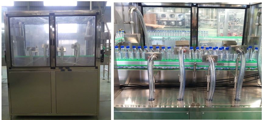
Features:
- The blower adopts a fan as the air source.
- An air knife type structure, and the size of the sealing can be adjusted.
- The top side and the two vertical sides of bottles can be blown to dry thoroughly.
- Easy for labeling, printing, packing operations.
Technical parameters:
| Model: | INP-CGJ |
| Capacity: | 6000 B/H |
| Length: | 800 mm |
| Dimension of the blower: | 40*40 mm |
| Power: | 7.5 kW * 2 |
| Material: | Stainless steel 304 |
| Dimension: | 1200*350*1400 mm |
Hot-melt glue labeler
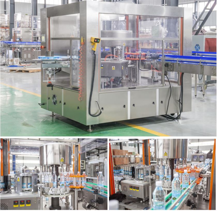
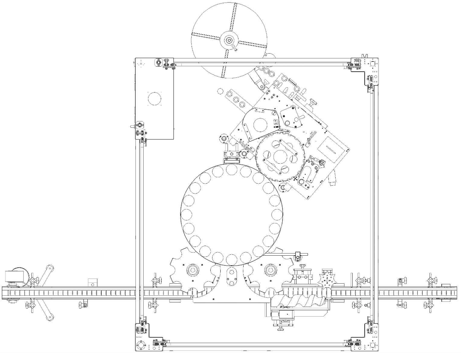
Mechanical parts
Transportation institution: Italy TRANSTECNO motor 0.75Kw (with deceleration by MOTOVARIO), inverter speed control
Conveyor: Italy FLEXON LF820-K325 industrial nylon chain plate conveyor
Mainframe transportation institution: Italy TRANSTECNO AC motor 2200W (with deceleration by TRANSTECNO)
Sub bottle institution: industrial worm sub bottle institution
Into bottle institution: with worm sub bottle institution and star wheel position feeding institution to ensure the accuracy and stability of loading
Position institution: Mechanical pre-location, using the cam-wheel institution to planish the bottle for label positioning
Labeling institution: Containers are pick up by rotary wheel, labeling during the rotation.
Supply label institution: High speed servo opp label supply system (drive by servo-motor)
Pressing label institution: Arc brush unit
Guided bottle institution: Adjust by double coordinate section guide rail
Glue supply system: Hot-melt glue supply system (Germany SEIMEC control system) ensures the accuracy and uniformity of gluing
Safety part of the machine
Safety protection: To keep the operator safety, when the machine is running, please close the protective doors
Lack of label alarm: Set an alarm to remind the operator to change the label when the label will be use out
Lack of bottle alarm: When lack of the bottle the machine will stop and make an alarm. The machine will restart automatically as soon as the bottles have been put that will facilitate on-line production
Leak of labeling alarm: To control the quality of labeling
Pressure testing: When the pressure cannot meet the equipment requirement, the machine will stop to against bad products produce
Vacuum testing: When the vacuum cannot meet the equipment requirement, the machine will stop to against bad products produce
Temperature testing: When the temperature cannot meet the equipment requirement, the machine will stop to against bad products produce
Method of Operation:
The containers are picked up by the in-feed star-wheel and transferred to the container table. The container rotation begins when they are positioned between container plates and centering bells.
The speed of the feed roller is adjusted to the required label length for continuous web tension. A standard threading unit ensures optimal film feed. In the cutting unit, the labels are precisely cut while a PLC command and servo-motor provide an exact cut-off point.
Two narrow strips of hot-melt glue the labels together, which are applied by a heated glue roller to the leading and trailing label edges. The label with the glue strip on its leading edge is transferred to the container. This glue strip ensures an exact label positioning and a positive bond. As the container is rotated during label transfer, labels are applied tightly. Gluing of the trailing edge ensures proper bonding.
Process: In-feed bottle → pre-positioning → label cutting → gluing → labeling → label by press out → finish
Technical parameters:
| Model: | INP-R6H |
| Power supply: | Three-phase 380V 50 Hz 10000W |
| The total length of equipment: | 3000mm (conveyor length 3000mm or can be regulate base on your product lines) |
| Equipment width: | 2300mm |
| Conveyor speed: | 30m/min (the speed of the transmission lines can be adjusted according to actual production) |
| The method of speed adjustment: | uninterrupted – adjust rate |
| The largest Speed of labels feed: | maximum speed of 100 meters labels / min |
| The largest speed of labeling: | 6000 BPH |
| Labeling accuracy: | ± 1mm |
| Integrated Labeling accuracy: | ± 1mm |
| Product Size: | 500ml |
| Maximum label width: | 150mm |
| The maximum length of label: | 500mm |
| The maximum diameter of label: | 600mm |
| Paper core diameter: | 152 mm |
| Labeling glue: | leading and trailing edge gluing with hot melt |
| Gluing temperature: | 120~160℃ |
| Type of label: | opp label, paper-plastic composite film label, paper label |
| Labeling workstation: | 20 per cycle |
| The quantity of labeling mold: | one suit (to be satisfied with one product, each mold contains infeed worm, in-feed star-wheel, discharge star-wheel, position bottle and so on) |
| Machine weight: | 3000 Kg |
Component list:
| Items | Supplier, Origin |
| Servo motor | Siemens, Germany |
| Servo drive | Siemens, Germany |
| Inverter | Siemens, Germany |
| Switch | Schneider, France |
| Breaker | Schneider, France |
| Relay | Schneider, France |
| Emergency stop switch | Schneider, France |
| PLC Programmable Controller | Siemens, Germany |
| Touch-screen | Siemens, Germany |
| Fiber Cable | KYENESE, Japan |
| Fiber amplifier | KYENESE, Japan |
| Electric eye test | SUNX, Japan |
Shrink Packer


Features:
- Classic shape, beautiful, novel structure, unique, easy operation and maintenance. The use of pneumatic expansion support film roll, electronic sensor film delivery, sending film stable, fast and convenient for membrane.
- Unique threat shaking bottle can make the product smooth separation, avoiding the phenomenon of squeeze bottle.
- Feeding conveyor and host length is 1.6 meters longer than other company, is conducive to the sorting of the bottles, effectively increasing the number of membrane rods to reduce the transmission line speed and increase the tolerance of equipment performance.
- Shrink chamber using a unique circular air supply technology to achieve multi-directional air flow control technology, adjustable wind speed, adjustable outlet position, greatly improving the shrinking effect.
- Shrinkage chamber using the newly developed open structure outside to facilitate maintenance; thick insulation layer, energy-saving effect, high temperature control accuracy.
- Man-machine interface: B&R LCD color screen, user-friendly interface, parameter setting fast.
- Electrical Configuration: More than 90% of the whole electrical components are imported high-quality brands. After 10 years of optimal configuration, it is stable and reliable.
- The machine adopts energy-saving technology design, saving 30% power loss, low-carbon, environmental protection.
Technical parameters:
| Model: | INP-MB40 |
| Working voltage: | Three-phase-five –line 380V/50Hz, 48KW
Control voltage: IN24V |
| Working pressure: | 0.6~0.8Mpa (without oil without water)
Air consumption: 80-100NL/min Pipe Joint Size: Φ10 |
| Packing speed: | 30-32packs/min |
| Shrink chamber: | L×W×H=2500×700×450(mm) |
| Shrink temperature: | 160℃~230℃ |
| Packing: | LDPE (dust & static electricity removed) |
| Width of film roll: | ≤580mm |
| Thickness of film: | 0.06~0.10mm |
| Thickness of film: | 0.06~0.10mm |
| Diameter of film roll: | ≤350mm |
| Film reel diameter: | 76mm |
| Working noise: | ≤65dB |
| Installed capacity: | 58 kW |
| Tall weight: | 4500Kg |
Component list:
| Items | Supplier, Origin |
| Servo motor &control system | B & R, Austria |
| PLC | B & R, Austria |
| Touch-screen | B & R, Austria |
| Transducer | DANFOSS, Denmark |
| Approach switch | LEUZE, Germany |
| Rising film cylinder | FESTO, Germany |
| Contactor | SEIMENS, Germany |
| Press adjusting device | MINDMAN, Taiwan |
| Intermediate relay | SCHNEIDER, France |
| Conveyor motor | SEW, Germany |
Air conveyor
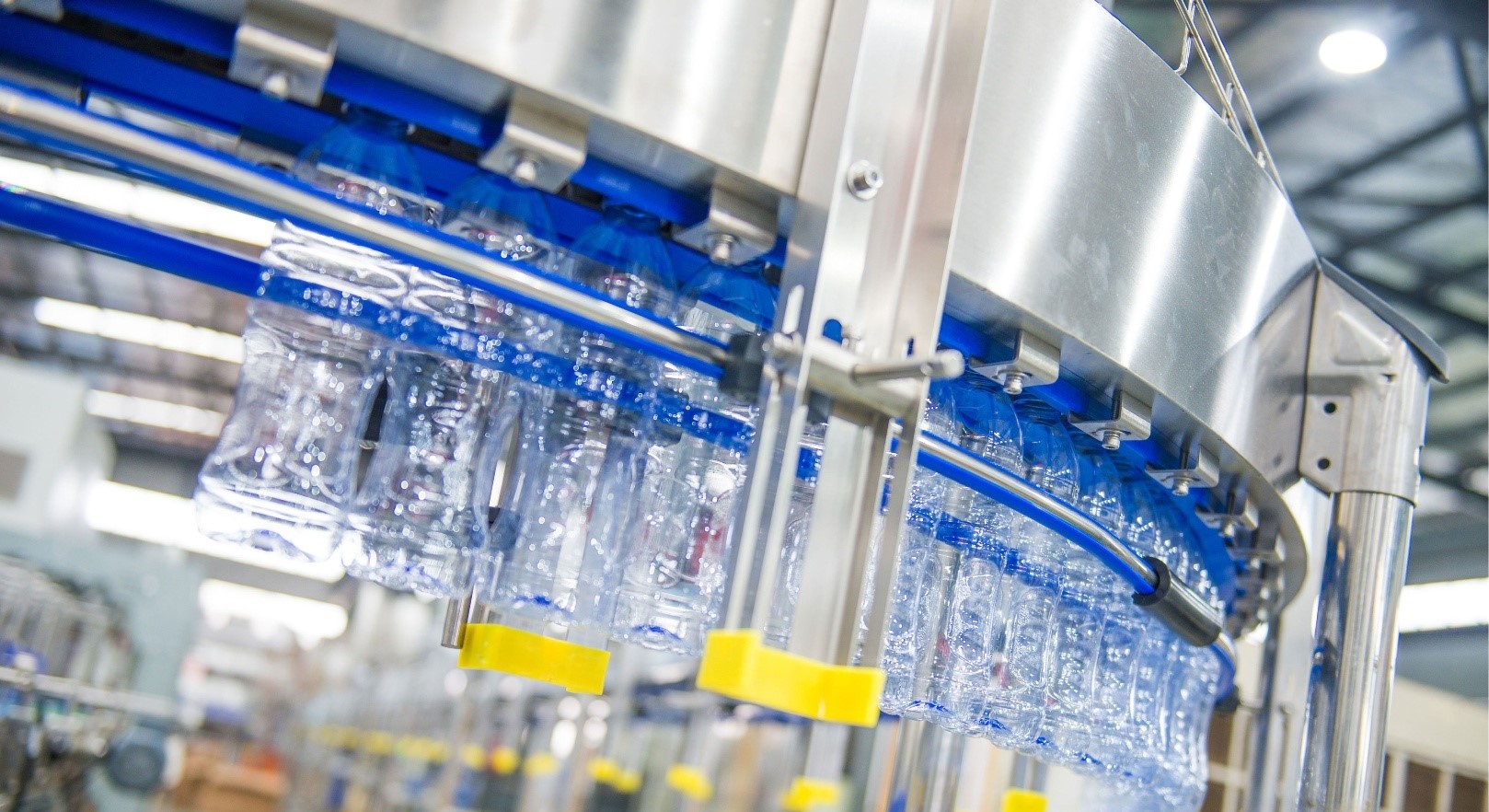
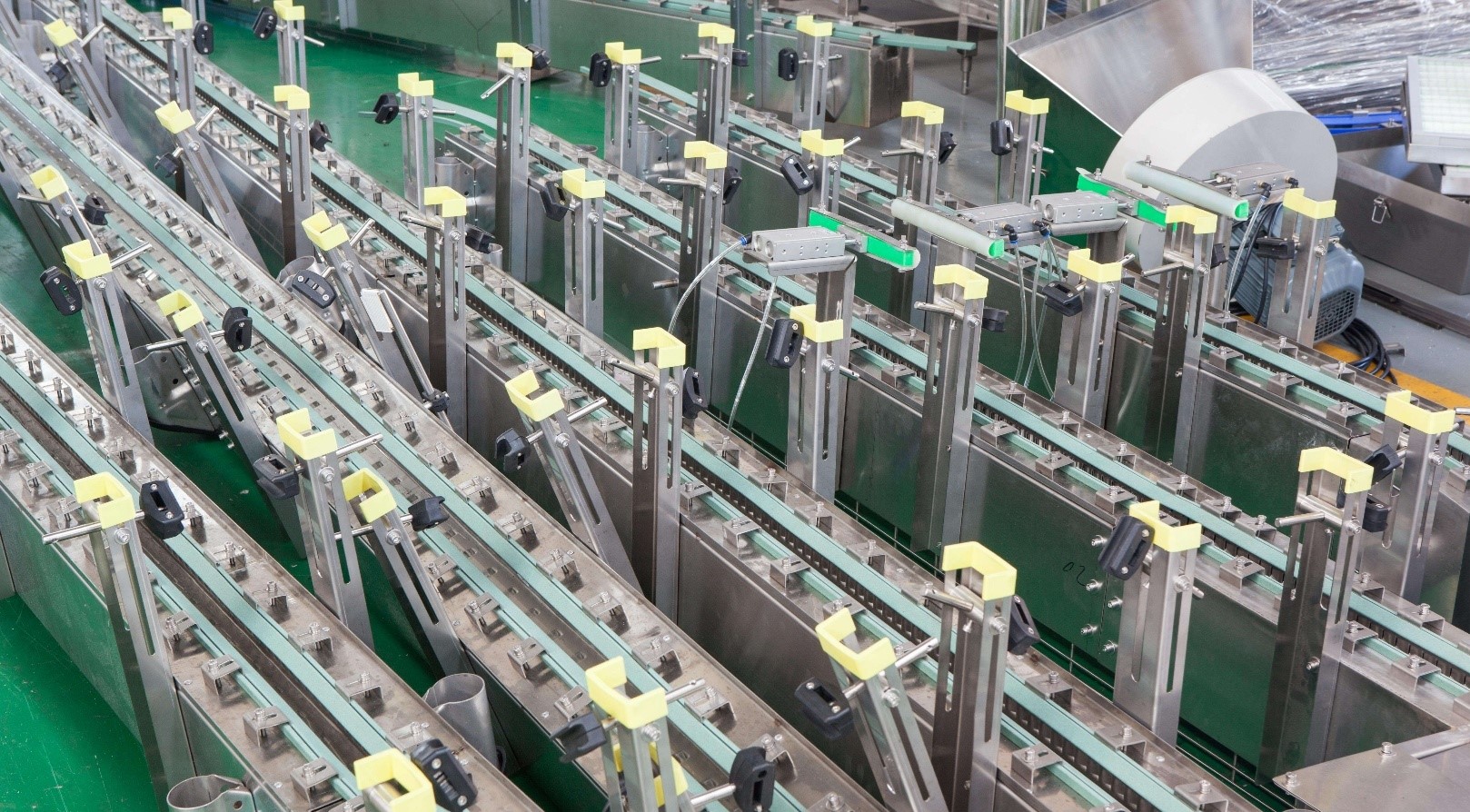
Description:
The air conveyor is installed on the supporting legs which are against the ground, and the fan is installed on the air conveying duct. The air inlet of each fan is equipped with an air filter to prevent dust from being blown into the container. The bottles are hung on the air conveyor by neck and transported to the rotary filler by air.
The automatic drop-off device is installed on the air conveyor, and the mechanism is driven by the cylinder. When the downstream machine has a temporary shutdown or deceleration operation, as the empty bottles on the air conveyor reach a certain amount, shut down the bottle-dropper to collect bottles from blowing machine manually, and put bottles back to the air conveyors afterward, this ensures that the blow molding machine does not have to turn off in this case.
There are multiple sets of photoelectric switches on the air conveyor. The photoelectric switch near the air crossroads is used to control the direction of the air blowing. The other photoelectric switches are used to control the automatic drop-off device, ensuring the smooth running of the entire air conveyor.
- Main body is made of Stainless Steel 304.
- The fan blowers have in-built air filters, avoiding secondary pollution.
- The air inlet of the fan outside the sterile room is equipped with a primary air filter to prevent dust from getting into the room.
Technical parameters:
| Fan power: | 2.2 kW / 5m |
| Cross-section size of the air channel: | 180*180 mm |
| Height | 1300 mm |
| Thickness of the steel plate: | 2 mm (SUS304) |
| Capacity of blowing: | ≥3400 m³/h |
| Filter type: | Plate type |
| Filter material: | Galvanized steel plate for out frame, stainless steel for filter screen |
| Filter size: | 610*610*102 mm |
| Bottle size: | 200-3000 ml |
| Bottle diameter: | 50-120 mm |
| Climbing angle of air conveyor: | ≤15° |
| Initial resistance: | ≤55 Pa, (final resistance is 4-5 times stronger than initial resistance) |
Belt conveyor & Buffering system
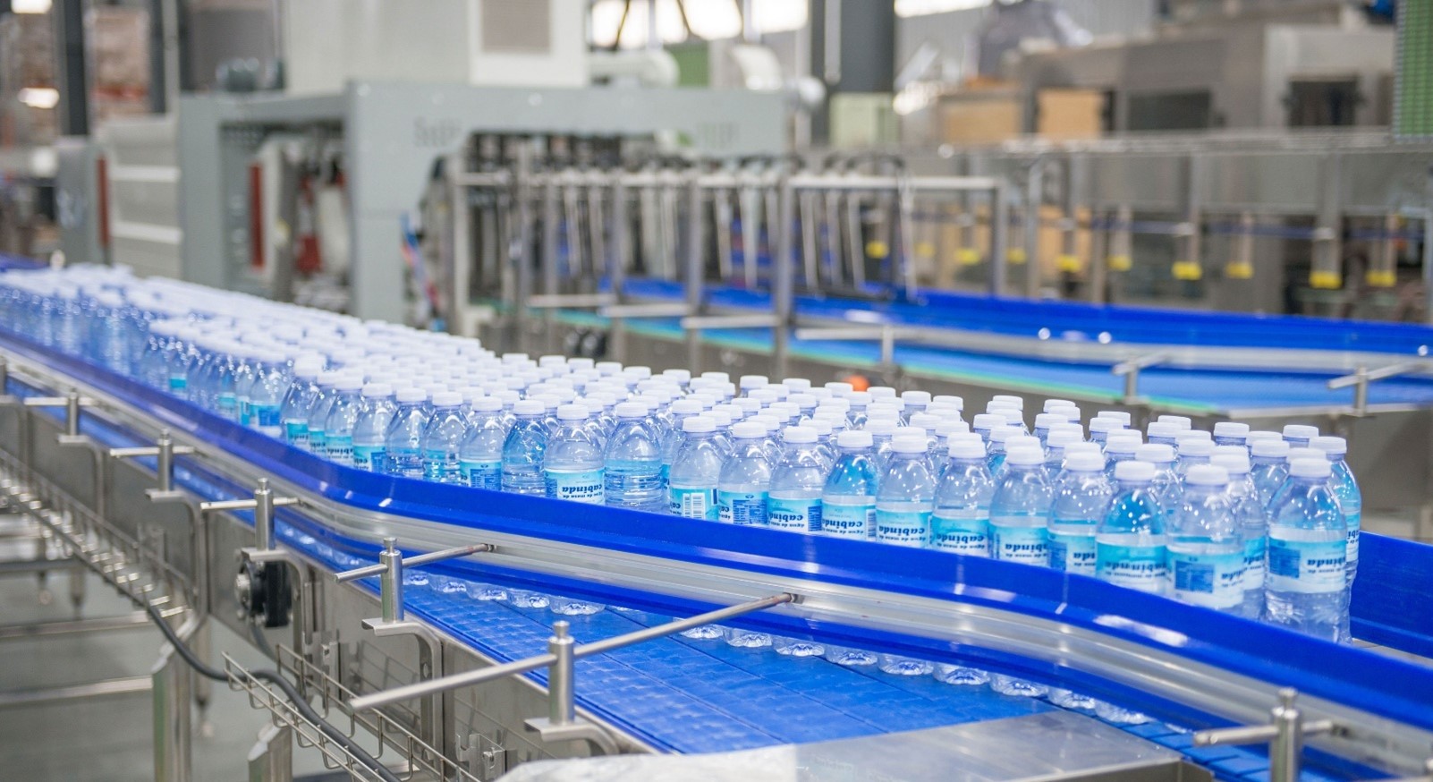
Description:
The operation efficiency of the production line is mostly up to the configuration of the conveyor line. The configuration must take into account the short-term shutdown of the rear-end equipment (for example, replacement of labels, etc.), ensuring the shutdown doesn’t affect the operation of the front-end equipment, and should be able to connect the front equipment and rear equipment well to make the whole the production line achieve high operation efficiency. Our production line’s layout fully considers the relationship between customer investment and production line efficiency. Based on the world’s advanced technology, the above requirements can be well achieved. The mechanical structure is a new design, most of the components are formed by stamping or bending, which has the advantages of good rigidity, light weight and good interchangeability. The transmission method features reliable operation and convenient maintenance, which is suitable for conveying bottles with diameters of Ø40-Ø110mm. The electric control system adopts PLC (On the Rinsing-filling-capping tri-block) to control the operation of the whole container conveying buffer system, and automatically conduct the functions of running speed acceleration and deceleration and automatic buffering.
Features:
- The bottle belt is synchronously tracked with the host or the upstream and downstream equipment, which are connected to control system.
- The bottle does not fall, does not jam, and does not block during the conveying process.
- According to the user’s needs, the buffer platform can be set in front of the labeling machine (the buffering time is usually about 1-2 minutes).
- When replenish PE label, the filling process proceeds, the filled bottles are stored on the buffer platform. After finishing replenishing PE label, the labeler starts labeling, the line gets back to synchronizing production.
- After replenishing, the labeling machine produces at a higher speed to fill the platform with labeled bottles again, and then resumes the synchronous production speed.
- The conveyor belt structure is modular design, the parts are interchangeable, compact, low noise, easy to install and maintain, and can be combined according to different capabilities and bottle types, which has great flexibility.
- Electric control design is advanced and reasonable, and the control method can be designed according to the customer’s requirements, and the required electrical control components can be selected to further improve the smoothness of transportation.
- The control switch position is reasonably set according to the layout of the conveying system or the customer’s demand, which is convenient for the user to operate.
Technical parameters:
| Motor power: | 0.37 kW / 6m |
| Width of the conveyor: | 110 mm |
| Height: | 1050 mm |
| Thickness of the steel plate: | 2 mm (SUS304) |
| Bottle volume: | 200-3000 ml |
| Bottle Diameter: | 50-100 mm |
SUPPLIER AND CUSTOMER RESPONSIBILITIES
| DESCRIPTION | RESPONSIBILITY | |
| Supplier | Buyer | |
| Building | ||
| Any civil engineering works and foundations for equipment installation | √ | |
| Drainage and disposal of all waste (water, liquids, gas, dust), such as lubricant for conveyors, CIP, warm air, ventilation, etc. up to the drain point (SUS 304) | √ | |
| Cranes and lifting rails for work | √ | |
| Pipe & cable racks, footbridges, stairs, platforms, ways through conveyors | √ | |
| Cabinets and shelves to store molds, tools and adaptation parts for extra bottle formats | √ | |
| Any civil engineering works or carpentry not clearly listed and described. | √ | |
| Lighting, heating, air conditioning system, grounding system | √ | |
| Machinery ground support and fixing | √ | |
| City water and city gas | √ | |
| Product preparation and conditioning | ||
| Syrup room, product preparation and treatment technology and relevant piping, only if included in the scope of supply | √ | |
| Piping between syrup room, product preparation and treatment technology and the supplied equipment take-over point, including safety measures for the circuits in compliance with the relevant regulations. | √ | |
| Piping thermal insulation | √ | |
| Cabling, cable trays and supports between the above equipment and filling line (automation signal exchange) | √ | |
| CIP for the equipment not included in the scope of supply | √ | |
| Consumables and Raw Materials | ||
| Supply and shipment of all the materials (such as preforms or bottles, caps, labels, glue, ink, cardboard, films, pallets, etc.) for the Delivery test at Supplier’s premises within the agreed deadline (DDP) | √ | |
| All consumables for start-up, acceptance test and industrial production, (such as preforms bottles, caps, labels, glue, ink, cardboard, films, pallets, product to be conditioned, detergents, oil, grease, filters, first fill of hydraulic oil, etc.) | √ | |
| Production of energy and fluids | ||
| Installation and supply of quantity and quality in full compliance with the Supplier’s requirements for: | ||
| Compressed air | ||
| Service low pressure air supply and relevant compressor | √ | |
| DESCRIPTION | RESPONSIBILITY | |
| Supplier | Buyer | |
| Compressor for high pressure (HP) (Only for Blowing Machine) air supply | √ | |
| Chilled water | ||
| Chiller for cooling water supply for blower | √ | |
| Chiller for cooling water supply for product | √ | |
| Steam | ||
| Steam production | √ | |
| Sterile air | ||
| Sterile air production | √ | |
| Foam | ||
| Foaming station for external cleaning of the supplied equipment | √ | |
| Cleaning in place (CIP) | ||
| Cleaning in place for cleaning of supplied equipment internal circuits | √ | |
| Electric Power | ||
| Plant Main electrical Power Supply | √ | |
| Surge protectors against overvoltage: tension stabilizers, harmonic filters, transient voltage suppressors | √ | |
| Power supply for INPAKT equipment (Main Distribution Panel) excluding blower, compressors (high and low pressure) for blower, cooling tower (or free cooler) and chiller for blower | √ | |
| Power supply (Main Distribution Panel) for blower, compressors (high and low pressure) for blower, cooling tower (or free cooler) and chiller for blower | √ | |
| Power supply for Syrup room, product preparation and treatment technology, only if included in the scope of supply | √ | |
| Emergency power generator and relevant transformers, Frequency converter and interconnecting cables/trays | √ | |
| Distribution of energy and fluids | ||
| Details of the connection specifications to the Supplier/Buyer interfaces (please check the layout, for the specific limit of supply of Connections Points) | √ | |
| Compressed air | ||
| Stainless steel distribution piping and connections between the supplied equipment and the HP air network | √ | |
| Stainless steel distribution piping and connections between the supplied equipment and the LP air network | √ | |
| Cooling water piping between compressors and cooling tower (or free cooler) | √ | |
| Water | ||
| DESCRIPTION | RESPONSIBILITY | |
| Supplier | Buyer | |
| Stainless steel distribution piping and connections between the supplied equipment and the city water, treated water and hot water | √ | |
| Cooling water distribution piping between chiller and cooled equipment inlet connection | √ | |
| Piping insulation of chilled and hot water network | √ | |
| Steam and CO2 | ||
| Steam and CO2 distribution piping between production (or feeding) point and the supplied equipment | √ | |
| CIP and COP | ||
| Piping between CIP and Supplier’s machines | √ | |
| Piping between COP and Supplier’s machines | √ | |
| Aeraulics | ||
| All air ventilation and exhaust from Supplier’s machines to the discharge points | √ | |
| Heat extraction hood above the Blow Moulder oven (interlocking with machine main drive) | √ | |
| Ducting of hot air extraction for compressor, chiller, cabin dehumidifier and PET dryer | √ | |
| Electric Power | ||
| Power supply (cabling and cabletrays) to the Main Distribution Panel. | √ | |
| Cabling, cable trays and supports between filling line conveyor panel and conveyors | √ | |
| Cabling, cable trays and supports from the Main Distribution Panel to the Cabinets of the equipment supplied by INPAKT (excluding blower, compressors (high and low pressure) for blower, cooling tower (or free cooler), chiller for blower.) | √ | |
| Cabling, cable trays and supports from the Main Distribution Panel to the Cabinets of blower/injection machine, compressors high and low pressure) for blower, cooling tower (or free cooler), chiller for blower/injection machine. | √ | |
| Cabling, cable trays and supports for Syrup room, product preparation and treatment technology, only if included in the scope of supply | √ | |
| Internal wiring of the INPAKT supplied equipment among machine cabinets where applicable (interface signal cabling) | √ | |
| Discharges and draining collection | ||
| Piping to connect the plant and the INPAKT’s machinery and conveyors discharge points | √ | |
| Project Management | ||
| Definition and integration of new equipment with existing plant equipment (if applicable) | √ | √ |
| Project launch meeting | √ | √ |
| DESCRIPTION | RESPONSIBILITY | |
| Supplier | Buyer | |
| Project planning | √ | √ |
| Global engineering coordination for INPAKT supplied equipment | √ | |
| Equipment Inspection and reception at the plant | √ | |
| Equipment Shipment coordination according to general sales conditions of the present offer | √ | |
| Installation drawings and assembly procedures | √ | |
| Installation planning | √ | |
| Installation start-up meeting | √ | √ |
| Coordination of installation | √ | |
| Training & documentation | ||
| Training | ||
| On the job “First Level” training of the Buyer’s operators by INPAKT Staff (practical training on the line using standard manuals) at Buyer’s premises. | √ | |
| Travel, board & lodging and local transportation expenses of Buyer’s personnel during training at Supplier’s premises (only if included in the scope of supply) | √ | |
| Formal “Advanced” Training of the Buyer’s operators by INPAKT staff (classroom training, followed by training on the line, using standard manuals + specific training material when needed) (max 6 people) ) at Buyer’s premises. (only if included in the scope of supply) | √ | |
| Local interpreter to support Supplier’s teacher during training session and his relevant expenses, for non-English lessons. | √ | |
| Equipment operation and maintenance manual | ||
| One CD Rom of manuals | √ | |
| Installation, commissioning & acceptance tests | ||
| Arrival of the equipment | ||
| Custody of crates in a safe and blind area pending unpacking | √ | |
| Custom clearance | √ | |
| Machinery and Lifting Tools for unloading of the equipment | √ | |
| Unloading insurance coverage | √ | |
| Inspection of the equipment by local authorities (if required) | √ | |
| Crates unloading | √ | |
| Supervision of equipment unloading | √ | |
| Unpacking and positioning of equipment | ||
| Crate opening (Unpacking) | √ | |
| Handling and positioning of the equipment | √ | |
| Handling and positioning insurance coverage | √ | |
| Machinery and Lifting Tools for equipment arranging and positioning | √ | |
| Supervising of equipment positioning | √ | |
| DESCRIPTION | RESPONSIBILITY | |
| Supplier | Buyer | |
| Installation, commissioning and acceptance test | ||
| Disassembling and/or adaptation of existing machines | √ | |
| Supervision for installation and assembly of the supplied equipment | √ | |
| Skilled labour for installation and assembly of the supplied equipment | √ | |
| Technicians for tests and start-up | √ | |
| Machines operators for production test, start-up, commissioning and acceptance test | √ | |
| Special equipment/tools | ||
| Necessary tools for operations at the installation site (high power drill, hand grinder, hydraulic jack, rollers cropper, etc.) | √ | |
| Machinery and tools for possibly working at heights (ladder, scaffolding unit) | √ | |
| Tools for possible welding and piping works (welder, saw) | √ | |
| Consumables for mechanical workings and welding (gas, lubricants, pickling paste, cleaning, etc..) | √ | |
| Logistic | ||
| Work Authorization for the Supplier’s personnel on site (if required) | √ | |
| Locked room for storage of tools and personnel changes of clothing | √ | |
| Locked room for storage of Supplier’s spare parts required for operations support | √ | |
| Telephone and fax line available, high speed internet connection and conditioned meeting room | √ | |
| Local interpreter to support Supplier’s engineers (if required) | √ | |
| Miscellaneous | ||
| Consumables and utilities for the installation phase (water, electric power, air, …) and relevant connections and piping | √ | |
| Raw material losses, product losses, production losses during tests and starting up | √ | |
| Delays resulting in additional manpower costs for reasons not due to the Supplier | √ | |
| Additional manpower costs as a result of night shifts or bank holidays | √ | |
| Thorough cleanup of the work site and equipment | √ | |
| Miscellaneous | ||
| All equipment or service explicitly described in the relevant offer | √ | |
| Any other equipment or service not clearly described in the present offer | √ | |
| Travel expenses of Supplier’s personnel or Supplier’s contractors | √ | |
| Board & lodging and local transportation expenses of Supplier’s personnel or Supplier’s contractors | √ | |


